Outlook on Modular Shoring Systems in Construction
The industry is moving toward standardized, quick-connect modular shoring systems to cut setup time and improve load traceability. Buyers should plan for digital documentation, mixed-system compatibility, and stricter inspection regimes. This guide outlines five shifts in concrete shoring systems and how to prepare your procurement strategy.
- Standardized modular components are replacing bespoke pole-and-pipe layouts to reduce on-site fit-up time.
- Digital load documentation is becoming the norm, moving shoring verification from paper checklists to mobile apps.
- Procurement must account for mixed-system compatibility, as projects often combine different shoring products.
- Inspection regimes are tightening around base plate bearing capacity and prop bracing geometry.
- Buy standard sizes first and reserve custom lengths for edge conditions and irregular spans.
Why Modular Shoring Is Gaining Ground
The default shoring layout for a concrete slab used to be a pole-and-pipe system. Workers cut, welded, and adjusted each joint on site to match the formwork span. That method works, but it creates friction. Every joint is a potential weak point. Every adjustment adds time to the pour cycle.
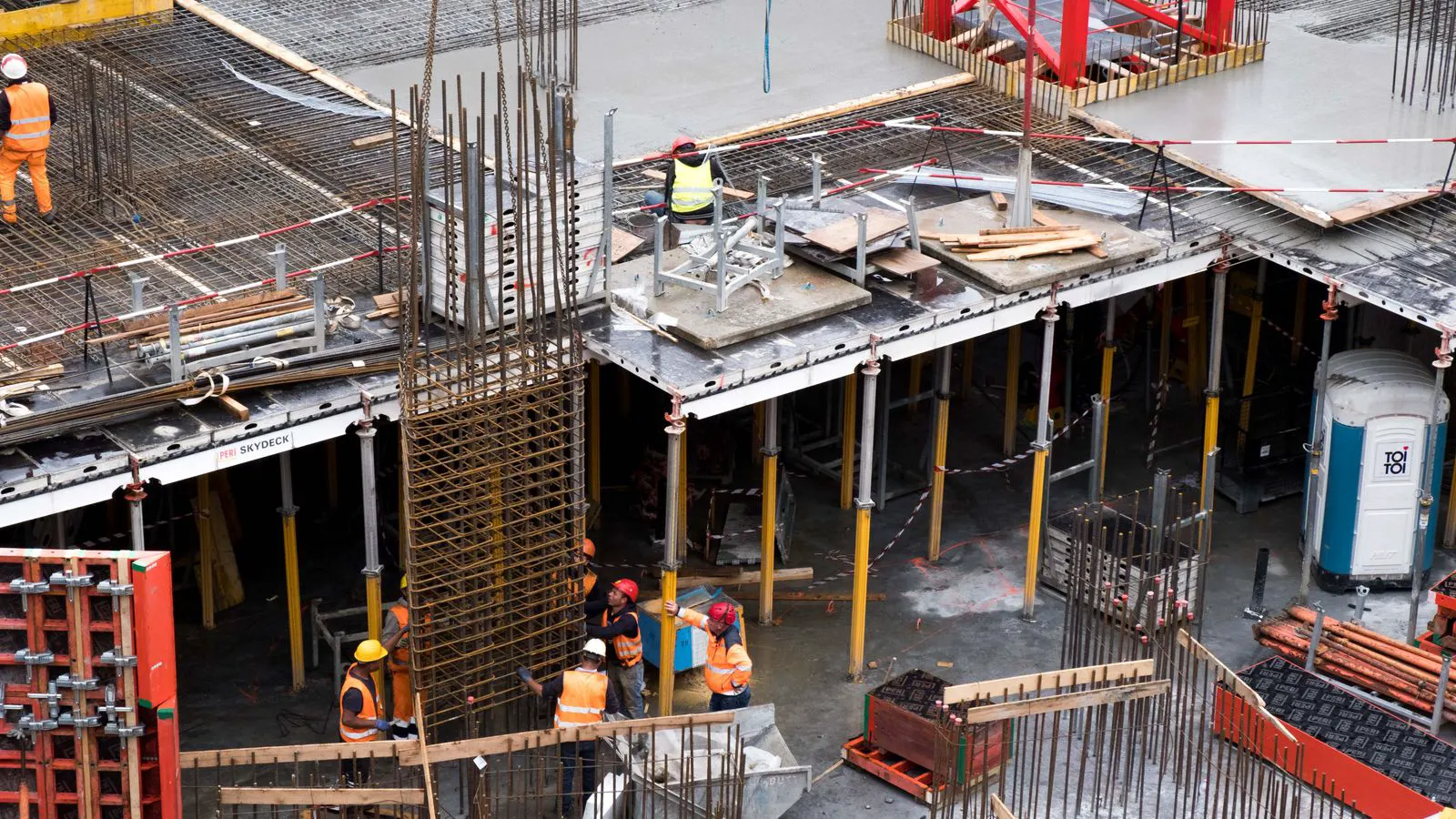
Modular shoring systems are changing that friction. A modular set uses standardized, prefabricated components. The vertical prop, the base plate, the head plate, and the brace are all sized to connect to one another without field modification. The result is a faster setup and a clearer understanding of how the system carries load.
This shift is not just about speed. It is about control. When every component is from the same standardized range, the engineer can verify the load path more easily. The contractor can inspect the system more quickly. The buyer can inventory parts with fewer SKU variations. For teams planning multiple pours across a site, that consistency pays off.
Shift One: From Custom Builds to Standard Kits
The first shift buyers should plan for is the move from custom pole builds to standard kits. A custom build involves selecting individual lengths of pipe and coupling every joint. A standard kit comes in defined sizes. The supplier provides a load chart for each size. The contractor picks the kit that matches the span and the concrete unit weight.
The advantage is not just speed. It is auditability. If a site inspector asks for the load capacity of a specific prop, the answer comes from a printed plate or a digital catalog. There is no need to trace back to a cut list or a field note.
This also changes procurement. Instead of buying a bin of 6m, 9m, and 12m pipes, a contractor buys a set number of kits. The kits include base plates, head plates, and braces in the matching size. The inventory is smaller. The site is cleaner. The risk of a missing coupling is lower.
The trade-off is rigidity. A standard kit does not cover every span. If a formwork bay is 3.2m wide but the kit only covers 3.0m and 3.6m, the contractor must bridge the gap. That usually means adding a second row of props or using a custom-length prop for the edge. The plan must account for this up front.
Shift Two: Digital Load Documentation
The second shift is the move from paper checklists to digital load documentation. Traditional shoring verification used a clipboard. The engineer drew the layout. The contractor signed off on the setup. The inspector checked the base plates. The paper sat in a file cabinet for the project duration.
Digital tools are changing that. A mobile app can store the shoring layout as a 2D or 3D model. The app links each prop to its load rating. The inspector scans a QR code on the base plate and the app shows the required load and the actual load. The photo is timestamped and stored in the project record.
This does not replace the engineer. It gives the engineer a clearer picture. The digital record shows the exact configuration at the time of the pour. If a dispute arises later, the record is available. The inspector can see the bracing geometry and the base plate condition. The contractor can show that the setup matched the engineered plan.
The practical benefit is faster sign-off. The inspector no longer needs to compare the site to a hand-drawn sketch. The app shows the expected layout. The inspector checks the actual site against the model. The match is immediate. The sign-off takes minutes, not hours.
Shift Three: Mixed-System Compatibility
The third shift is the recognition that most sites will use mixed systems. A large concrete pour will not use a single shoring product from start to finish. The core will use heavy-duty modular props. The edge will use a lighter system. The temporary support for a beam might use a different product entirely.
Buyers must plan for compatibility. If the site uses two different modular shoring systems, the props must be interchangeable. The base plates must fit the same head plates. The braces must connect to the same coupling. If they do not, the site becomes a jumble of incompatible parts. The setup slows down. The inspection becomes harder.
This is where standardization helps. Industry groups are working toward common coupling diameters and common base plate dimensions. The goal is not to force one product onto every site. The goal is to make different products work together. A contractor can buy the primary system from one supplier and the edge system from another, and still have a coherent shoring layout.
The buyer should ask suppliers for compatibility sheets. These sheets show which base plates and head plates work with which props. The buyer should also ask about brace compatibility. A brace that fits a 60mm prop may not fit a 75mm prop. The mismatch can create a weak point at the connection.
Shift Four: Stricter Inspection of Base and Head Plates
The fourth shift is the tightening of inspection around base and head plates. The vertical prop carries the load, but the connection points carry the load too. A base plate with a cracked edge can fail under a point load. A head plate with a deformed coupling can slip.
Inspection is moving beyond a visual check. The inspector is now expected to check the base plate bearing area. The plate must be flat. The edge must be intact. The surface must be clean. The concrete below must be firm. A soft or uneven base can cause the prop to tilt.
The head plate inspection is similar. The coupling must be square. The plate must be level. The prop must be plumb. A slight tilt in the prop can create a lateral load that the brace must resist. If the brace geometry is off, the load path changes.
This shift means the contractor must invest in inspection tools. A spirit level is a minimum. A digital inclinometer is better. A torque wrench is needed for the couplings. The tools are cheap, but they change the discipline. The inspector is no longer guessing. The inspector is measuring.
Shift Five: Standardized Load Charts and Digital Integration
The fifth shift is the standardization of load charts and the digital integration of those charts. A load chart tells the buyer the maximum load a prop can carry. It also tells the buyer the maximum span the prop can support without a brace. It tells the buyer the required base plate size for a given load.
The problem with traditional load charts is that they are paper documents. They are often outdated. They are often not the same across suppliers. The contractor must keep multiple charts in a folder. The inspector must find the right chart for the right product.
Digital integration solves this. The load chart lives in the supplier’s app or the project management software. The contractor selects the prop size and the app shows the load capacity. The app also shows the required base plate size and the brace spacing. The chart is always current. The inspector can access it from a tablet.
This also helps with procurement. The buyer can generate a cut list or a kit list from the digital chart. The chart accounts for the specific span and the specific concrete unit weight. The list is accurate. The site has the right parts. There is no over-ordering. There is no under-ordering.
How to Prepare Your Procurement Strategy
The table below summarizes the shifts and the actions a buyer should take. The goal is not to adopt every trend at once. The goal is to plan for them.
| Shift | Buyer Action |
|---|---|
| Standard kits | Buy standard sizes first. Reserve custom lengths for edges and irregular spans. |
| Digital documentation | Choose suppliers with mobile load charts. Integrate the app into the project management system. |
| Mixed-system compatibility | Ask for compatibility sheets. Ensure base plates and couplings match across products. |
| Stricter inspection | Invest in inspection tools. Train inspectors on base plate and head plate checks. |
| Standardized load charts | Use digital load charts. Generate kit lists from the app. |
The first step is to review the current shoring inventory. Identify the products that are still in use. Identify the products that are being replaced. The goal is to phase out custom builds and move to standard kits. The transition does not need to happen in one pour. It can happen over a season.
The second step is to review the supplier relationship. Ask the current supplier about their modular shoring range. Ask about the load charts. Ask about the digital tools. If the current supplier does not offer these, look for a new one. The supplier must be able to support the digital documentation and the inspection requirements.
The third step is to train the site team. The modular system is simpler, but it is not automatic. The workers must understand the connection points. The workers must know how to check the base plate. The workers must know how to verify the prop plumbness. The training should be hands-on. The team should set up a test layout and inspect it.
The fourth step is to update the inspection procedure. The current procedure may rely on visual checks. The new procedure must include measurements. The inspector must check the base plate bearing area. The inspector must check the head plate coupling. The inspector must check the brace geometry. The procedure must be written and signed off.
What to Avoid
The first mistake to avoid is assuming that modular shoring is a drop-in replacement. It is not. The load path is different. The connection points are different. The inspection requirements are different. The team must be trained on the new system. The engineer must verify the load path. The inspector must check the connection points.
The second mistake is to ignore the edge conditions. The modular system works best for the center of the span. The edge of the span is different. The edge may require a different base plate. The edge may require a different brace. The edge may require a custom length. The plan must account for this.
The third mistake is to skip the digital integration. The digital tools are not optional. They are the core of the system. The load chart is in the app. The inspection record is in the app. The project record is in the app. If the app is not used, the system is not working as intended.
Final Thoughts
The outlook on modular shoring systems is clear. The industry is moving toward standardization, digital documentation, and stricter inspection. The buyer must plan for these shifts. The procurement strategy must change. The site team must be trained. The inspection procedure must be updated.
The goal is not to adopt every new product. The goal is to build a shoring system that is faster to set up, easier to inspect, and easier to verify. The modular system makes that possible. The buyer who prepares now will be ready when the market shifts. The buyer who waits will be the one scrambling to catch up.
Frequently asked questions
How much does a modular shoring system cost compared to a traditional pole-and-pipe system?
The upfront cost of a modular system is often higher because the components are specialized. The long-term cost is lower because the setup time is shorter and the inspection is faster. The exact cost depends on the project size and the number of pours.
Can I mix modular shoring with my existing pole-and-pipe system?
You can mix them if the connection points are compatible. The base plates and couplings must match. If they do not match, the setup will be slower and the inspection will be harder. Check the compatibility sheets before mixing.
What is the biggest risk with a modular shoring system?
The biggest risk is using the wrong size for the span. The modular system is standardized, but it does not cover every span. If the span is outside the standard range, the load path changes. The engineer must verify the layout.
How often should I inspect the base plates?
Inspect the base plates before every pour. Check the edge for cracks. Check the surface for deformation. Check the bearing area. The base plate is the first point of failure if it is damaged.
Do I need a new engineer to design the modular shoring layout?
You do not need a new engineer. You need an engineer who understands the modular system. The load path is different from a traditional system. The engineer must verify the connection points and the brace geometry.